JK1SXR
=>Japanese
Return to "A. Home"
1. Antenna and
child view
2. IC-746 LCD
back-light repair
3. Oscilloscope and
stray magnetic flux
4. VX-5 main switch
restoration
5. Gagarin 55
6. DP vs discone
for air bands
7. First station
CW 1-watt
8. First station
Vertical ANT + DC-7D
9. First station
First QSO
10. PC renewal
Data transfer mystery
C. SXR radio notes
3. Oscilloscope and leakage magnetic flux
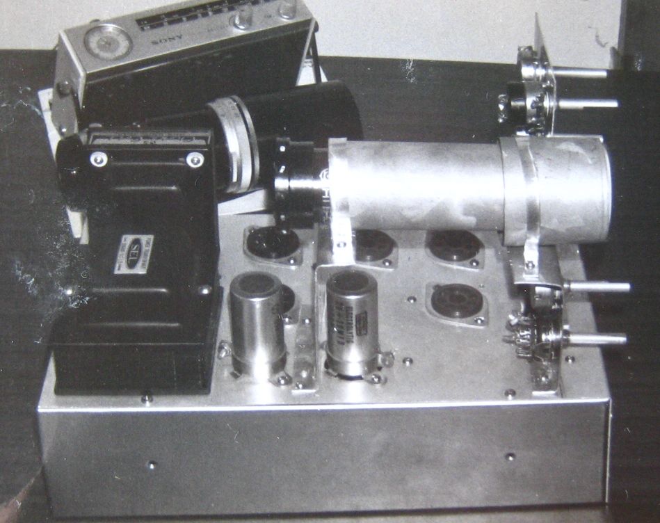
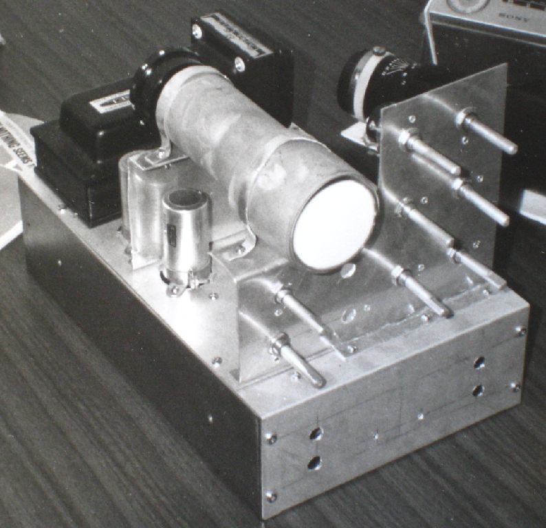 The photos are for an oscilloscope with a mere 2-inch screen under construction, probably just before or after 1970 as it was 2 or 3 years after I started working. I was making this night after night. So the story is for more than 45 years back.
These are from picture prints, and their quality is not so good but could be good enough for this explanation.
At those days, vacuum tubes were still used, and most of this type of equipment could be assembled by myself. I also made a low frequency oscillator requied for the operation check of this oscilloscope.
This was built by referring to a book titled "Amateurs' oscilloscope technologies" / OHM Paperback No. 45 / by Enami Toshisaburo of JVC. The book has aged too much and turned yellowish, the 17th edition published in S37 (1962), June 30th, priced 240 yen. Its 1st edition was published in S29 (1954).
Initially this was built on a breadboard, and showed fine waves, to my delight, when a signal of the low-frequency oscillator was applied. However I noticed the spot at no signal which should appear on the center of the 2-inch screen looked not a real dot, but a very short vertical line, 1 mm or so.
I could have neglected such minor thing but could not. I was curious what caused that line. After wasting a time trying this, that and the others for a week or so, I realized that the vertical line remained vertical even if I rotated the Braun tube itself.
As I immediately understood, that aha, this is the trick by the so-called stray magnetic flux, this problem was solved by encapsulating the total lenght of the CRT by galvanized steel plates as in the picture. The photos here are for the one assembled again on a new chassis for putting it in a housing, after confirming this setup working fine.
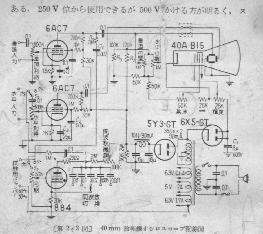
P70. Fig. 2.3 / OHM Book No.45 / "Amateurs' oscilloscope technologies"
This is the circuit diagram of the above book.
The vacuum tube marked with 884 at the bottom looks like a pentode, but it is a gas-filled triode, thyratron, as a round dot is indicated beside the grid electrode.
This tube generates the sawtooth voltages for sweeping, and at the same time synchronizes with the signals to be measured.
Copyright © 2013 JK1SXR/abemasa. All Rights reserved.